A heat exchanger is a device that transfers heat between two fluids without mixing them. To size one, you calculate the heat duty Q, find the log mean temperature difference (LMTD), and solve Q = U × A × F × ΔTlm for the required area A. When outlet temperatures are unknown, use the effectiveness-NTU method instead. This guide explains the main types, both methods, and two worked examples with every number checked in Python.
What a heat exchanger does
A heat exchanger moves thermal energy from a hotter fluid to a colder one across a solid wall, usually metal. The two streams stay separate, so a lubricating oil can be cooled by water, or a refrigerant can be condensed by air, without contamination. You will find them in power plants, refrigeration and air-conditioning systems, chemical plants, and vehicles, where radiators, oil coolers and intercoolers are all heat exchangers. For a vehicle-focused view, see our guide on how diesel engines work, where the cooling circuit is one important example.
Sizing balances three things: the duty, the driving temperature difference, and the overall heat transfer coefficient. Area connects them.
Main types of heat exchangers
Shell-and-tube
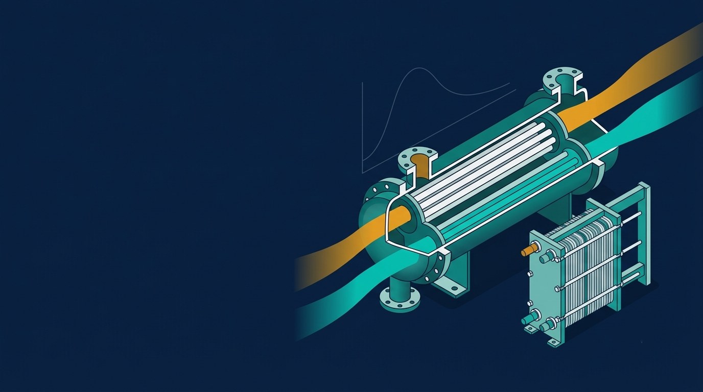
A bundle of tubes sits inside a cylindrical shell. One fluid flows in the tubes, the other across the tubes in the shell, guided by baffles. It is the workhorse of refineries, chemical plants and power stations because it handles high pressure, high temperature and large duties, and can be opened for cleaning. Design is commonly governed by TEMA (Tubular Exchanger Manufacturers Association) standards.
Plate heat exchangers
Thin corrugated plates are stacked with gaskets (or brazed/welded) to form alternating hot and cold channels. The corrugations create turbulence at low flow rates, so U is high and the unit is compact. Gasketed types can be opened and extended, but gaskets limit pressure and temperature.
Double-pipe
One pipe inside another. It is simple, cheap and easy to arrange in true counterflow, but it needs a lot of length for large duties. It suits small duties and high-pressure service.
Finned-tube and air-cooled
When one fluid is a gas or air, its heat transfer coefficient is low, so fins add surface area on that side. Car radiators, air-conditioning coils and air-cooled condensers use this approach. Air-cooled exchangers avoid the need for cooling water, which matters in water-scarce locations.
Spiral, plate-fin, printed-circuit and rotary regenerative exchangers serve specialised duties with the same basic equations.
| Type | Typical use | Advantages | Limitations |
|---|---|---|---|
| Shell-and-tube | Refineries, power plants, high-pressure duties | Robust; high pressure and temperature; standardised (TEMA) | Bulky; lower U than plates; cleaning bundle needs space |
| Gasketed plate | Food, HVAC, water-water duties | Compact; high U; easy to clean and expand | Gasket limits on pressure and temperature; higher pressure drop |
| Double-pipe | Small duties, high-pressure lines | Simple; true counterflow; cheap | Large length per kW; not for big duties |
| Finned-tube / air-cooled | Radiators, condensers, coils | No cooling water; fins offset weak gas-side h | Large face area; fan power; fouling of fins |
Parallel flow vs counterflow
In parallel flow both fluids enter at the same end and move the same way. The temperature difference is large at the inlet and shrinks toward the outlet, and the cold outlet can never exceed the hot outlet. In counterflow the fluids enter at opposite ends. The temperature difference stays more uniform, so for the same terminal temperatures the LMTD is larger and less area is needed. Counterflow is the most thermally efficient arrangement. The worked example below shows the difference in numbers.
The basic sizing equation and the LMTD
The rate equation for a heat exchanger is:
Q = U × A × ΔTlm (for pure parallel or counterflow)
where Q is heat duty in W, U is the overall heat transfer coefficient in W/m²·K, A is the heat transfer area in m², and ΔTlm is the log mean temperature difference in K. Duty comes from an energy balance on either stream: Q = ṁ cp ΔT, with ṁ in kg/s and cp in J/kg·K.
The LMTD is:
ΔTlm = (ΔT₁ − ΔT₂) / ln(ΔT₁ / ΔT₂)
For counterflow, ΔT₁ = Th,in − Tc,out and ΔT₂ = Th,out − Tc,in. For parallel flow, ΔT₁ = Th,in − Tc,in and ΔT₂ = Th,out − Tc,out. If ΔT₁ equals ΔT₂, the LMTD equals that common value (the formula gives 0/0).
Correction factor F for multipass and cross-flow
Real shell-and-tube exchangers with multiple tube passes, and cross-flow units, are not pure counterflow. You apply a correction factor: Q = U × A × F × ΔTlm,cf, where the LMTD is calculated as if the exchanger were counterflow. F is less than or equal to 1 and depends on two dimensionless groups, P = (Tc,out − Tc,in) / (Th,in − Tc,in) and R = (Th,in − Th,out) / (Tc,out − Tc,in). F is read from charts in textbooks such as Incropera and Cengel, or from TEMA and design software; for a 1-2 shell-and-tube there is also a closed-form expression. As a rule of thumb, designers try to keep F above about 0.8 because the design becomes very sensitive to small changes below that, and a low F signals that more shells in series may be needed.
Overall heat transfer coefficient U and fouling
U combines the resistances between the two fluids: the hot-side film, any fouling layer on each side, the wall, and the cold-side film. Per unit area (neglecting curvature):
1/U = 1/hh + Rf,h + t/k + Rf,c + 1/hc
Fouling is the deposit of scale, biological growth, corrosion products or sediment. It adds thermal resistance Rf (m²·K/W) and reduces U over time. Designers include a fouling allowance so the exchanger still meets its duty when dirty. Typical fouling resistances are of the order of 0.0001 to 0.0005 m²·K/W depending on fluid and velocity; take exact values from TEMA tables for your service.
The table below gives indicative ranges for U. These vary widely with velocity, geometry and fluid properties, so treat them only for first estimates.
| Fluid pair | Indicative U (W/m²·K) |
|---|---|
| Water to water | 800 to 1,500 |
| Oil to water | 100 to 400 |
| Steam (condensing) to water | 1,000 to 3,500 |
| Gas to water | 20 to 300 |
| Air to air | 10 to 50 |
Indicative only. Always confirm against your textbook tables, vendor data or calculated film coefficients.
Worked example 1: sizing an oil cooler (LMTD method)
Problem. A counterflow oil cooler must cool lubricating oil from 90 °C to 60 °C. Cooling water enters at 25 °C. Find the required heat transfer area.
Assumptions and given data (steady state, no heat loss to surroundings, constant properties, all inputs assumed for illustration):
- Oil mass flow: 2.0 kg/s, cp = 2,100 J/kg·K
- Water mass flow: 1.5 kg/s, cp = 4,180 J/kg·K
- Overall U = 350 W/m²·K (clean, assumed)
Step 1: Duty. Q = 2.0 × 2,100 × (90 − 60) = 126,000 W = 126 kW.
Step 2: Water outlet. Tc,out = 25 + 126,000 / (1.5 × 4,180) = 45.10 °C.
Step 3: LMTD (counterflow). ΔT₁ = 90 − 45.10 = 44.90 K, ΔT₂ = 60 − 25 = 35 K. LMTD = (44.90 − 35) / ln(44.90 / 35) = 39.75 K.
Step 4: Area. A = Q / (U × LMTD) = 126,000 / (350 × 39.75) = 9.06 m² (clean).
What changes with other assumptions?
- Parallel flow: ΔT₁ = 65 K, ΔT₂ = 14.90 K, LMTD = 34.02 K, so A = 10.58 m², about 17% more area than counterflow.
- Fouling: add assumed fouling resistance of 0.0003 m²·K/W in total. Dirty U = 1 / (1/350 + 0.0003) = 316.7 W/m²·K, so A = 10.01 m², about 10% more than clean.
- 1-2 shell-and-tube: P = 0.309 and R = 1.493 give F = 0.933 from the closed-form 1-2 expression, so A = 126,000 / (350 × 0.933 × 39.75) = 9.71 m² (clean).
In practice you would size for the fouled case and then check pressure drop, velocities and mechanical layout.
Effectiveness-NTU method
The LMTD method is convenient when all four temperatures are known or computable. If you have an existing exchanger (known area and U) and want to predict the outlet temperatures, LMTD needs iteration. The effectiveness-NTU method avoids that.
Define the heat capacity rates C = ṁ cp for each stream. Let Cmin be the smaller and Cmax the larger, and Cr = Cmin/Cmax. Then:
- NTU = U A / Cmin (number of transfer units)
- Effectiveness ε = Q / Qmax, where Qmax = Cmin (Th,in − Tc,in)
- For counterflow: ε = [1 − exp(−NTU (1 − Cr))] / [1 − Cr exp(−NTU (1 − Cr))], and ε = NTU / (1 + NTU) when Cr = 1
Use NTU when you are rating an existing exchanger, when outlet temperatures are unknown, or when comparing designs with different flow arrangements. Relations for other arrangements are tabulated in Incropera and Cengel.
Worked example 2: predicting outlet temperatures (NTU method)
Problem. An existing water-to-water counterflow exchanger has A = 4.0 m² and U = 800 W/m²·K (assumed). Hot water enters at 80 °C at 1.0 kg/s; cold water enters at 20 °C at 1.2 kg/s. Both cp = 4,180 J/kg·K. Find the outlet temperatures.
- Ch = 1.0 × 4,180 = 4,180 W/K; Cc = 1.2 × 4,180 = 5,016 W/K
- Cmin = 4,180 W/K, Cr = 0.833
- NTU = 800 × 4.0 / 4,180 = 0.766
- ε = 0.450 (counterflow equation)
- Qmax = 4,180 × 60 = 250.8 kW, so Q = 0.450 × 250.8 = 112.7 kW
- Th,out = 80 − 112,735 / 4,180 = 53.0 °C; Tc,out = 20 + 112,735 / 5,016 = 42.5 °C
No iteration was needed. Note that the hot stream here is the Cmin stream, so it shows the larger temperature change.
Python snippet
This script reproduces both examples.
import math

def lmtd_counterflow(t_hi, t_ho, t_ci, t_co):
    dt1 = t_hi - t_co   # hot inlet vs cold outlet
    dt2 = t_ho - t_ci   # hot outlet vs cold inlet
    if dt1 <= 0 or dt2 <= 0:
        raise ValueError("Temperature cross: check your temperatures")
    if abs(dt1 - dt2) < 1e-9:
        return dt1
    return (dt1 - dt2) / math.log(dt1 / dt2)

def eff_counterflow(ntu, cr):
    if abs(cr - 1) < 1e-9:
        return ntu / (1 + ntu)
    e = math.exp(-ntu * (1 - cr))
    return (1 - e) / (1 - cr * e)

# Example 1: area from LMTD
q = 2.0 * 2100 * (90 - 60)              # W
t_co = 25 + q / (1.5 * 4180)            # degC
lmtd = lmtd_counterflow(90, 60, 25, t_co)
area = q / (350 * lmtd)
print(f"Q = {q/1000:.1f} kW, Tc,out = {t_co:.2f} C, LMTD = {lmtd:.2f} K, A = {area:.2f} m2")

# Example 2: outlet temperatures from NTU
c_h, c_c = 1.0 * 4180, 1.2 * 4180
c_min, c_max = min(c_h, c_c), max(c_h, c_c)
ntu = 800 * 4.0 / c_min
eps = eff_counterflow(ntu, c_min / c_max)
q2 = eps * c_min * (80 - 20)
print(f"NTU = {ntu:.3f}, eps = {eps:.3f}, Q = {q2/1000:.1f} kW, "
      f"Th,out = {80 - q2/c_h:.1f} C, Tc,out = {20 + q2/c_c:.1f} C")
Output: Q = 126.0 kW, Tc,out = 45.10 C, LMTD = 39.75 K, A = 9.06 m2 and NTU = 0.766, eps = 0.450, Q = 112.7 kW, Th,out = 53.0 C, Tc,out = 42.5 C.
Common mistakes
- Temperature cross. If the cold outlet exceeds the hot outlet in a single-pass exchanger that is meant to be counterflow, check the numbers. If ΔT₁ or ΔT₂ is zero or negative, the LMTD is invalid, and the design is thermodynamically infeasible or needs multiple shells.
- Ignoring fouling. A clean-U design can fall short within months. Size with a fouling allowance.
- Ignoring pressure drop. Smaller area with high velocity raises U but also pumping power. Check pressure drop against the pump or fan available.
- Wrong F or low F. Using F = 1 for multipass units understates area. An F below about 0.75 to 0.8 is a warning sign.
Limitations and professional design
The methods here are first-pass estimates. They assume steady state, constant U and properties, negligible heat loss, and no phase change in single-phase equations. Condensing, boiling, two-phase flow, vibration, thermal stress, and mechanical design of pressure parts need specialised methods. This article is educational and is not a substitute for TEMA and standards-based professional design, or for validation by a qualified engineer or a vendor’s rating software before procurement or installation. Thermal loading also matters for engines; our article on why diesel engine duty cycles decide engine life shows how operating conditions drive cooling demand.
Frequently asked questions
Which is better, LMTD or NTU?
Neither is more accurate; they are equivalent. Use LMTD for sizing when all temperatures are known, and NTU for rating or when outlet temperatures are unknown.
Why is counterflow more efficient than parallel flow?
It keeps a more uniform temperature difference along the length and allows the cold outlet to approach or exceed the hot outlet temperature, which gives a larger LMTD for the same terminals.
How much fouling allowance should I add?
It depends on fluid, temperature, velocity and cleaning interval. Take values from TEMA fouling tables or plant experience, and confirm with the customer or vendor.
What if F comes out very low?
Increase the number of shells in series, change the pass arrangement, or reconsider the terminal temperatures. A low F means the arrangement is thermally inefficient.
Sources to check
- Incropera, DeWitt, Bergman and Lavine, Fundamentals of Heat and Mass Transfer (Wiley), heat exchanger chapter for LMTD, F charts and effectiveness-NTU relations.
- Yunus A. Cengel, Heat and Mass Transfer: Fundamentals and Applications (McGraw-Hill), heat exchanger chapter and typical U and fouling tables.
- Donald Q. Kern, Process Heat Transfer (McGraw-Hill), classic shell-and-tube design methods.
- TEMA (Tubular Exchanger Manufacturers Association) Standards, for mechanical design and fouling guidance in shell-and-tube exchangers.
Edition and table values vary between books, so check the edition you use. All example inputs in this post are assumed for illustration.
Every formula you need, in one place
The Mechanical Engineering Formula Handbook covers 140+ core formulas across 12 subjects, with symbols, SI units and notes on when to use each one. Ideal for exams and quick checks at work. Want the full kit? The Engineer Toolkit Bundle adds calculators, Excel practice and AI prompts for engineers.
Prefer video? Watch the tutorials on YouTube · Browse all toolkits