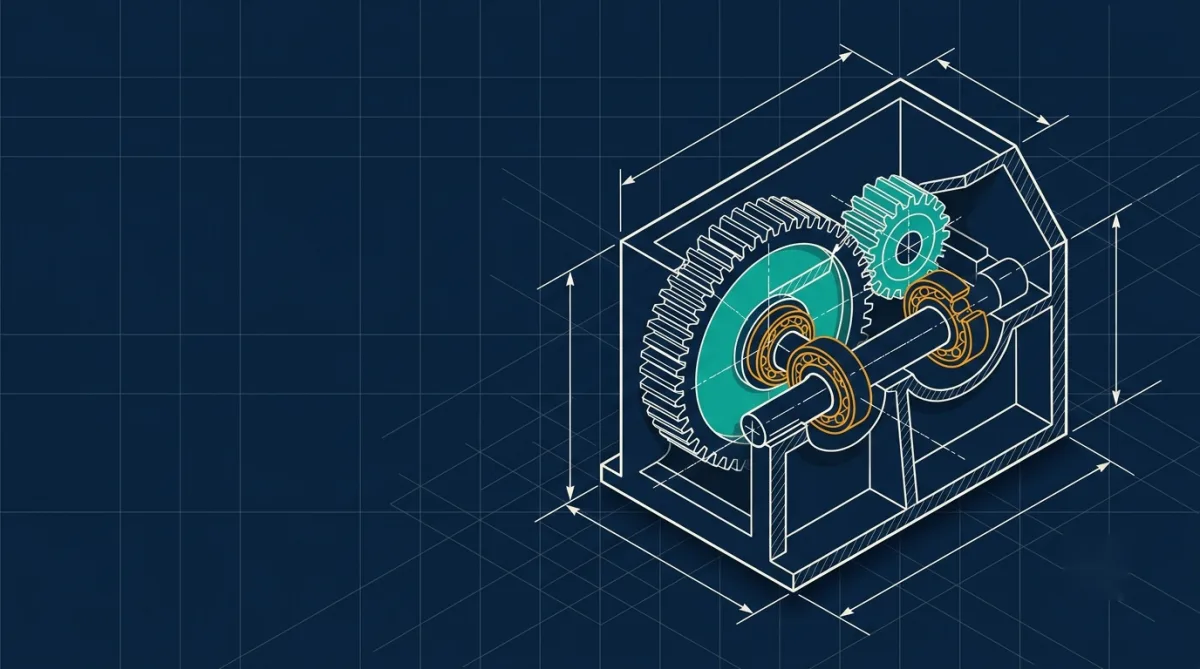
A Engineering Analysis of Planetary Gear Systems from Antiquity to High-Performance Additive Manufacturing
The architecture of modern motion control is fundamentally defined by the planetary gear set, a mechanism that started from the sophisticated analogue computing of the Hellenistic era to the high-torque, energy-dense drivetrains of the twenty-first century.
Often referred to as epicyclic gearing, this system utilizes a central sun gear, multiple orbiting planet gears, and an outer ring gear to achieve a remarkable concentration of power within a compact spatial envelope. For the modern engineer, the planetary gear is not merely a component but a masterpiece of geometric synchronization, offering a versatility that traditional parallel-shaft systems cannot match.
To understand its profound impact, one must look beyond the immediate mechanical utility and investigate the underlying mathematical constraints, the nuances of load distribution, and the historical milestones that have shaped its development.
The Historical Genesis of the Epicyclic Concept

The narrative of planetary gearing begins not in a modern industrial laboratory, but in the depths of a shipwreck near the Greek island of Antikythera in 1901. Divers recovered a calcified, bronze device that would eventually be recognized as the oldest known analogue computer, the Antikythera Mechanism. Dating to approximately 150 – 100 BCE, this device utilized over thirty gear wheels in a shoebox-sized frame to perform complex astronomical calculations with a level of miniaturization that would not be replicated for another millennium.
At the heart of this ancient computer was a pioneering application of epicyclic gearing. While the device’s main purpose was to track the movements of the Sun, Moon, and known planets through the zodiac, its most sophisticated feature was its ability to model the “first anomaly” of the Moon the slight variations in its velocity as it moves from its perigee to its apogee.
This was achieved through a pin-and-slot mechanism integrated into an epicyclic gear train, translating the irregular elliptical motion of the Moon into a predictable mechanical display. The historical implications are staggering, suggesting that figures such as Archimedes or Hipparchus had already mastered the mathematical principles of gear ratios and orbital mechanics to a degree that allowed for the mechanization of the heavens.
| Historical Milestone | Estimated Date | Significant Technical Contribution |
| Antikythera Discovery | 1901 CE | Recovery of 82 fragments showing complex gearing. |
| Initial Construction | ~150–100 BCE | First known epicyclic gears for astronomical display. |
| Medieval Cathedral Clocks | 14th Century | Resurgence of complex geared mechanisms in Europe. |
| Differential Invention | 1575 CE | Modern re-invention of the epicyclic differential. |
| Antikythera X-ray Tomography | 2005 CE | Reveal of 37 meshing bronze gears and inscriptions. |
The Antikythera Mechanism served not only a pragmatic calendrical purpose but also a philosophical one, fulfilling Aristotelian ideals by proving that the mathematical riddles of the cosmos could be resolved through human engineering. This historical context is vital for the modern designer, as it highlights that the challenges of gear synchronization, backlash, and precision are perennial problems that have been tackled by engineers across millennia.
Geometric Design and Structural Fundamentals

The engineering of a simple planetary gear set (single stage) begins with a rigorous definition of its geometric parameters. Unlike a standard spur gear pair where two axes are fixed relative to each other, the planetary set introduces a mobile axis the planet carrier, which adds a layer of kinematic complexity. The system’s geometry is dictated by the requirements of the involute tooth profile, which ensures a constant velocity ratio during engagement and minimizes vibration.
Technical Nomenclature and Symbols
In a standard design utilizing SI Units and a consistent pressure angle, typically, the following nomenclature is established to facilitate calculation and modeling.
| Parameter | Symbol | Definition / Formula |
| Module | The ratio of pitch diameter to number of teeth (). | |
| Number of Teeth (Sun) | The tooth count of the central driving gear. | |
| Number of Teeth (Planet) | The tooth count of the orbiting gears. | |
| Number of Teeth (Ring) | The tooth count of the internal annulus gear. | |
| Number of Planets | The total number of gears mounted on the carrier. | |
| Pressure Angle | Angle of the line of action ( is standard). | |
| Pitch Diameter | ||
| Base Diameter | ||
| Center Distance | Distance between the sun and planet centers. | |
| Addendum | Height above the pitch circle (). | |
| Dedendum | Height below the pitch circle (). |
Geometric Constraints for Assembly
The physical assembly of a planetary gear set is governed by strict mathematical conditions. If these are not met, the gears will either fail to mesh or will be impossible to install symmetrically on the carrier.
The first condition is the center distance equivalence. For the sun, planets, and ring gear to fit within the same plane, the center distance from the sun to the planet must be equal to the distance from the planet to the ring gear. In a standard system, this translates to the tooth count relationship:
This formula assumes that all gears share the same module and have no profile shift. If a designer seeks to adjust the gear ratio or strengthen the teeth through profile shifting, the center distances must still be equalized (), necessitating a recalculation of the operating pressure angles and tooth thicknesses.
A second, and often overlooked, constraint is the planet-to-planet clearance. Because multiple planet gears are enclosed within the ring gear, there must be sufficient clearance between the tip diameters of adjacent planets to prevent “clashing”. The center distance between adjacent planets () must satisfy:
where is the tip diameter of the planet gear. The distance is a function of the center distance () and the number of planets ():
Finally, the most critical assembly constraint is the divisibility rule. For planet gears to be spaced evenly around the sun gear and still mesh correctly with both the sun and the ring gears, the sum of the teeth on the sun and ring gears must be an integer multiple of the number of planets :
Failure to satisfy this equation means that as the first planet gear is placed in mesh, the subsequent positions on the carrier will not align with the teeth of both the stationary and driving gears.
This constraint significantly limits the available ratios for a given planet count, often forcing designers to use prime numbers for tooth counts or to accept slightly unequal planet spacing, which can complicate the balance of the carrier.
The Mechanics of Variable Ratios

The versatility of the planetary gear set is derived from its ability to function in different modes depending on which of the three primary components sun gear, carrier, or ring gear is held stationary. This allows a single mechanical assembly to provide speed reduction, overdrive, or reverse rotation by simply applying a brake to one component.
The Three Fundamental Operational Modes
The kinematic behavior is generally analyzed through the Willis equation, which defines the relationship between the angular velocities of the sun (), ring (), and carrier ():
From this, the primary transmission ratios () for a single-stage system can be derived.
Mode 1: Planetary Configuration (Fixed Ring Gear)
In this mode, the ring gear is stationary (). The sun gear acts as the input and the carrier as the output. This is the most common configuration for industrial speed reducers and automotive wheel hubs.
Ratio Formula:
Characteristics: High torque multiplication, speed reduction, and same-direction rotation for input and output.
Mode 2: Solar Configuration (Fixed Sun Gear)
When the sun gear is held stationary (), the ring gear acts as the input and the carrier as the output. This is frequently used in specific industrial drives where moderate speed reduction is required.
Ratio Formula:
Characteristics: Low reduction ratio, same-direction rotation.
Mode 3: Star Configuration (Fixed Carrier)
By fixing the carrier (), the system acts as a simple idler gear train. The sun gear drives the planets, which rotate on fixed pins and drive the ring gear in the opposite direction.
Ratio Formula:
Characteristics: Speed reduction or increase depending on tooth counts, but fundamentally results in a reversal of output direction.
| Configuration Name | Stationary Part | Input Part | Output Part | Ratio Formula (R) | Rotational Direction |
| Planetary | Ring Gear | Sun Gear | Carrier | Same | |
| Solar | Sun Gear | Ring Gear | Carrier | Same | |
| Star | Carrier | Sun Gear | Ring Gear | Opposite |
The implications of these ratios are profound for machine design. For instance, in a Toyota Prius hybrid drivetrain, a planetary gear set acts as a power-split device, seamlessly blending power from the gasoline engine and the electric motor by varying the speeds of the different components. This ability to “sum” or “split” power is what differentiates the epicyclic system from its parallel-shaft ancestors.
Force Distribution and Torque Density
The primary reason for the widespread adoption of planetary gears in high-performance machinery is their superior torque density. In a standard parallel-shaft gearbox, the entire load is transmitted through a single mesh point between two gears. In a planetary system, the input torque is distributed across multiple planet gears, typically three to five.
Load Sharing and the Mesh Load Factor ()
Ideally, if there are four planet gears, each planet would carry exactly 25% of the total load. However, manufacturing inaccuracies, elastic deformation of the carrier, and thermal expansion lead to an unequal distribution of forces. The degree of this imbalance is quantified by the mesh load factor, :
In modern gear design standards such as ISO 6336, values typically range from 1.10 to 1.25. If the load sharing is poor (), the gears will suffer from localized tooth root stresses, leading to premature fatigue and failure. To mitigate this, advanced gearboxes utilize flexible planet pins or floating sun gears, which allow for small radial movements to “self-align” and equalize the mesh forces.
Torque and Force Calculations
The relationship between the torque on each component is dictated by the principle of mechanical advantage and the gear ratios. For a planetary configuration (fixed ring):
Sun Torque (): The input torque from the motor.
Ring Torque (): The reaction torque absorbed by the housing,
.
Carrier Torque (): The total output torque,
.
Because the forces at each mesh point are distributed, the radial loads on the sun gear bearings tend to cancel each other out in a perfectly symmetric three-planet system. This cancellation leads to a “pure” torsional transmission, reducing bearing friction and increasing the overall mechanical efficiency of the stage, which often exceeds 95%.
Planetary vs. Traditional Gearboxes
The selection between a planetary gearbox and a traditional parallel-shaft gearbox is a multi-objective optimization problem. While the planetary set offers compactness, it brings challenges in manufacturing and maintenance.
| Feature | Planetary Gearbox | Parallel Shaft Gearbox |
| Torque Density | High (Multi-path sharing) | Lower (Single mesh point) |
| Space/Weight | Compact and Lightweight (30-50% less) | Bulkier and Heavier |
| Alignment | Coaxial (Input/Output on same axis) | Offset (Parallel axes) |
| Efficiency | High (95-98% per stage) | Very High (up to 99%) |
| Complexity | High (Nested components) | Low (Simple mesh) |
| Manufacturing Cost | Higher (Precision requirements) | Lower (Cost-effective for standard ratios) |
The “kings of torque,” planetary gearboxes, are preferred when space and weight are at a premium, such as in aerospace actuation or the wheel drives of heavy mining equipment. Conversely, traditional gearboxes remain the industry standard for simple, high-speed applications where offset shafts are acceptable and budget is a primary constraint.
Critical Design Pitfalls and Interference Phenomena
Designing a planetary gear set is fraught with “interference” risks that are unique to internal-external gear meshing. Even if the tooth counts satisfy the assembly rules, the physical geometry of the teeth can clash.
Types of Internal Gear Interference
There are three primary interference patterns that engineers must check during the validation phase :

Involute Interference: This occurs when the tip of the internal gear tooth “digs” into the root of the pinion (planet gear) during the entry or exit phase of the mesh. It is typically caused by having too few teeth on the planet gear.

Trochoid Interference: This happens when the exiting planet tooth makes contact with the tip of the internal gear tooth after the mesh is technically complete. This is most common when the difference between the tooth counts of the ring and planet gear is small (e.g., <math data-latex=”z_r – z_p
Trimming Interference: This is a condition where the planet gear cannot be moved radially into mesh. It can be slid in or out axially, but the tips of the teeth prevent radial assembly.
Mesh Phasing and Vibration Control
Another second-order effect is “mesh phasing.” When multiple planet gears engage with the sun gear, their contact cycles may happen simultaneously (in-phase) or sequentially.
In-Phase Phasing: All planet gears engage a new tooth at the exact same moment. This reinforces the torque ripple and can lead to significant noise and vibration if the frequency matches a structural resonance.
Sequential-Phase: The engagement is staggered. This helps to smooth out the torque delivery and is often achieved by carefully selecting tooth counts that do not satisfy perfect symmetry but still meet the assembly conditions.
The classification of phasing is determined by the formula if , the system is in-phase, which creates high radial force cancellation but maximized torque reinforcement.
Strategic Applications Across Modern Industry
The unique kinematic and kinetic profile of planetary gears makes them indispensable in environments where reliability and density are the primary metrics of success.
Renewable Energy and Wind Power

In the wind energy sector, planetary gear technology is a linchpin. Wind turbine blades operate at very low speeds (often <15 RPM) but generate massive torque. To generate electricity, this must be stepped up to speeds of 1500–1800 RPM for the generator. Planetary gearboxes bridge this gap, handling the enormous torque levels while maintaining a compact nacelle size. Durability is crucial here, as these gearboxes must operate for 20+ years in harsh, inaccessible offshore environments.
Automotive and Electric Vehicles (EVs)

While traditional automatic transmissions use planetary sets to switch gears, electric vehicles utilize them for speed reduction. EV motors spin at very high RPMs (up to 20,000 RPM) to maintain efficiency and power density. A single-stage planetary gearbox reduces this to a usable wheel speed while fitting within the narrow constraints of an EV drivetrain. Furthermore, in hybrid vehicles like the Toyota Prius, the planetary set acts as a “Power Split Device,” managing the flow of power between the internal combustion engine and the electric motor-generators.
Aerospace and Aviation

In the aerospace sector, where every gram of weight translates to fuel cost, planetary gearboxes are used in jet engine accessory drives, helicopter rotor reductions, and satellite positioning mechanisms. These gears are frequently made from advanced materials like titanium or case-hardened alloy steels to survive high temperatures and extreme shock loads without failure.
| Industry | Primary Use Case | Key Performance Driver |
| Wind Energy | Speed Step-up (Blade to Generator) | Torque Handling & Reliability |
| Automotive | Automatic Transmissions & EV Reduction | Compactness & Efficiency |
| Aerospace | Actuation & Engine Power Transmission | Weight & Power Density |
| Robotics | Joint Actuators | Precision (Low Backlash) |
| Medical | Surgical Robots & Prosthetics | Miniaturization |
PEEK and 3D Printed Planetary Gears
The frontier of planetary gear technology is shifting from traditional metalworking to high-performance polymers and additive manufacturing. Polyetheretherketone (PEEK) has emerged as a viable metal replacement for gears in several mission-critical sectors.
Advantages of PEEK in Gear Design
The transition from metal to PEEK gears, especially those produced via technologies like Roboze 3D printing, offers several technical breakthroughs :
Self-Lubrication: PEEK is naturally self-lubricating with a low coefficient of friction. This eliminates the need for messy grease or oil systems, which is vital in medical devices, food processing, or space exploration where lubricants can outgas or freeze.
Weight Reduction: PEEK gears are up to 80% lighter than their brass or steel counterparts. This reduced mass decreases the inertia of moving parts, allowing for faster response times and higher energy efficiency.
Vibration and Noise Dampening: Unlike metal-on-metal contact, polymer gears absorb vibrations, leading to significantly quieter operation. This is a critical trend in the automotive industry for improving cabin comfort (“NVH” – Noise, Vibration, Harshness).
On-Demand Manufacturing: 3D printing allows for “dematerialization of the warehouse.” Instead of keeping thousands of spare gears in stock, companies can print a custom-designed gear “just-in-time”.
The market for high-performance 3D printed plastics is projected to grow significantly, reaching over USD 660 million by 2031. This shift is being driven by the aerospace and healthcare sectors, where patient-specific implants and lightweight drone actuators require the unique geometry that only 3D printing and epicyclic design can provide.
The Enduring Mastery of the Epicyclic System
The planetary gear set remains one of the most elegant and powerful configurations in the history of mechanical engineering. From its origins in the bronze calculators of ancient Greece to its modern role in the drivetrains of electric supercars, it has consistently represented the cutting edge of what is possible in motion control.
For the professional peer, the mastery of this system requires more than just a passing familiarity with its components. It demands a deep understanding of the mathematical constraints of tooth selection, a rigorous approach to mesh load factors (), and a forward-looking perspective on material science. As we move toward a future of increasingly electrified and automated systems, the ability to pack more torque into smaller spaces will remain a fundamental requirement. Whether realized through case-hardened steel or high-performance 3D-printed polymers, the dance of the sun and planets will continue to drive the machines that shape our world.
The evolution of the epicyclic system is a testament to the persistence of engineering logic. The same principles that allowed an ancient Greek astronomer to predict a lunar eclipse in 150 BCE are today allowing a wind turbine to harvest energy from the North Sea or a robotic arm to perform surgery with sub-millimeter precision. By understanding the geometry, kinematics, and kinetics of the planetary gear set, we don’t just solve a mechanical problem we engage with a lineage of ingenuity that spans over two thousand years.